Product Series
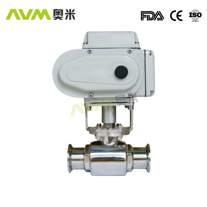
Electrical 2 Way Ball Valve
Classification:
keywords: Electrical 2 Way Ball Valve
Sanitary valves are key equipment widely used in industries such as pharmaceuticals, biotechnology, and food processing
E-mail:
Telephone:
Details
1、 Definition of Sanitary Valves
Sanitary valves refer to valves that meet strict hygiene requirements, and their design, manufacturing, and material selection are all based on meeting hygiene standards in industries such as food and medicine. This type of valve has the characteristics of no dead corners, easy cleaning, and corrosion resistance, ensuring the purity of the fluid during transmission.
2、 The function of sanitary valves
1. Flow control: Sanitary grade valves can accurately control the flow of fluids as needed, ensuring the stability of the production process and the quality of the product.
2. Preventing backflow: Valves can prevent fluid backflow and prevent pollutants from entering the production process.
3. Automation control: Some sanitary valves have automation control functions and can be linked with other equipment to achieve intelligent management of the production line.
3、 The role of sanitary valves in safeguarding human health
Sanitary valves, as important equipment in industries such as pharmaceuticals and food, play a crucial role in ensuring human health. Specifically, its role is reflected in the following aspects:
1. Ensure product safety: The application of sanitary valves can ensure the purity of fluids during transmission, thereby ensuring product safety.
2. Preventing cross contamination: The design of valves can prevent cross contamination between different fluids and reduce the risk of product contamination.
3. Improve production efficiency: Sanitary valves are easy to clean and maintain, which can greatly improve production efficiency and reduce production costs.
4. Reduce health risks: By precisely controlling flow and preventing backflow, sanitary valves can reduce potential risks to human health during the production process.
In short, sanitary valves play a crucial role in industries such as pharmaceuticals and food. Understanding and correctly applying sanitary valves is of great significance for ensuring product quality and human health. With the advancement of technology and the increasing demand for product safety, sanitary valves will play a more important role in the future.
Technical parameter
| Metal Material | Parts in contact with the product | 304L/316L(1.4307/1.4404) forging 304L/316L(1.4307/1.4404) Forged |
| Parts not in contact with the product | 304(1.4301) | |
| Provide EN 10204 3.1B certificate | ||
| Seal material | Standard | EPDM/PTFE |
| Optional | FPM/PTFE,HNBR/PTFE,Silicone/PTFE | |
| temperature | Continuous working temperature | -20~+135℃(EPDM) |
| Sterilization temperature | 150℃(max 20min) | |
| pressure | Work pressure | 0~5bar(standard) |
| Control air pressure | 5~8bar | |
| Surface treatment | Internal surface treatment | Ra≤0.8μm |
| External surface treatment | Matt | |
| connection | Connection standard | Welding end: DIN 11850 series 2 |
| Welding end: Inch pipe diameter standard | ||
| Connection method: welding, quick installation, thread\ and other common connection methods | ||

Size(mm)
| DIN | |||||||
| Size L | DN25 88 | DN32 88 | DN40 102 | DN50 102 | DN65 124 | DN80 152 | DN100 160 |
| H W | 74 130 | 79 130 | 95 170 | 100 170 | 125 200 | 136 250 | 144 250 |
| H1 W1 | 186 158.5 | 190 210.5 | 220 210.5 | 225 210.5 | 260 247.5 | 300 268.5 | 340 315 |
| OD M Clamp | 29×1.5 21.5 | 35×1.5 21.5 | 41×1.5 21.5 | 53×1.5 21.5 | 70×2.0 28 | 85×2.0 28 | 104×2.0 28 |
| M Clamp | - | - | - | - | - | - | - |
* For other connection methods, please contact Aomi Technical Department
| Inch | |||||||
| Size L | 1" 88 | 1-1/4" 88 | 1-1/2" 102 | 2" 102 | 2-1/2" 124 | 3" 152 | 4" 160 |
| H W | 74 130 | 79 130 | 95 170 | 100 170 | 125 200 | 136 250 | 144 250 |
| H1 W1 | 220 158.5 | 230 210.5 | 255 210.5 | 275 210.5 | 335 247.5 | 360 268.5 | 410 315 |
| OD M Clamp | 25.4×1.65 - | 31.75×1.65 - | 38.1×1.65 - | 50.8×1.65 - | 63.5×1.65 - | 76.2×1.65 - | 101.6×2.11 - |
| M Clamp | 12.7 | 12.7 | 12.7 | 12.7 | 12.7 | 12.7 | 15.8 |
* For other connection methods, please contact Aomi Technical Department
QF5-2 type

Size(mm)
| DIN | |||||||
| Size L | DN25 138 | DN32 148 | DN40 174 | DN50 184 | DN65 208 | DN80 256 | DN100 286 |
| H W | 72 160 | 75 160 | 82 180 | 120 230 | 123 280 | 145 310 | 160 310 |
| H1 W1 | 220 158.5 | 230 210.5 | 255 210.5 | 275 210.5 | 335 247.5 | 360 268.5 | 410 315 |
| OD M (Clamp) | 29×1.5 21.5 | 35×1.5 21.5 | 41×1.5 21.5 | 53×1.5 21.5 | 70×2.0 28 | 85×2.0 28 | 104×2.0 28 |
| M(Clamp) | - | - | - | - | - | - | - |
* For other connection methods, please contact Aomi Technical Department
| Inch | |||||||
| Size L | 1" 138 | 1-1/4" 148 | 1-1/2" 174 | 2" 184 | 2-1/2" 208 | 3" 256 | 4" 286 |
| H W | 72 160 | 75 160 | 82 180 | 120 235 | 123 280 | 145 310 | 160 310 |
| H1 W1 | 220 158.5 | 230 210.5 | 255 210.5 | 275 210.5 | 335 247.5 | 360 268.5 | 410 315 |
| OD M (Clamp) | 25.4×1.65 - | 31.75×1.65 - | 38.1×1.65 - | 50.8×1.65 - | 63.5×1.65 - | 76.2×1.65 - | 101.6×2.11 - |
| M(Clamp) | 12.7 | 12.7 | 12.7 | 12.7 | 12.7 | 12.7 | 15.8 |
* For other connection methods, please contact Aomi Technical Department
Schematic diagram of medium flow of three-way ball valve
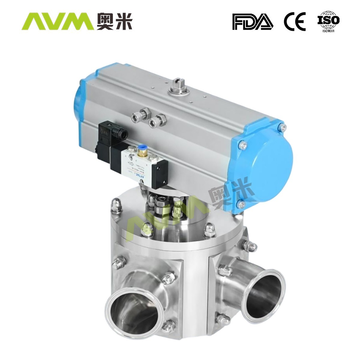
The three-way ball valve is used to split or merge flow. It is a multi-port ball valve with a two-sided or four-sided valve seat. Any port can be used as an inlet without leakage. The three links can be made into L-shaped ports or T-shaped ports.
Three-way ball valve structure
QF5-3 two-piece non-retention series
size(mm)
| DIN | |||||||
| Size | DN25 | DN32 | DN40 | DN50 | DN65 | DN80 | DN100 |
| L | 120 | 120 | 126 | 126 | 153 | 163 | 180 |
| H | 112 | 112 | 131 | 148 | 183 | 203 | 220 |
| W | 155 | 155 | 170 | 170 | 250 | 250 | 250 |
| HI | 220 | 230 | 255 | 275 | 335 | 360 | 410 |
| WI | 158.5 | 210.5 | 210.5 | 210.5 | 247.5 | 268.5 | 315 |
| OD | 29×1.5 | 35×1.5 | 41×1.5 | 53×1.5 | 70×2.0 | 85×2.0 | 104×2.0 |
| M Clamp | 21.5 | 21.5 | 21.5 | 21.5 | 28 | 28 | 28 |
| M Clamp | - | - | - | - | - | - | - |
* For other connection methods, please contact Aomi Technical Department
| Inch | ||||||
| Size | 1" | 1-1/2" | 2" | 2-1/2" | 3" | 4" |
| L | 120 | 126 | 126 | 153 | 163 | 180 |
| H | 112 | 131 | 148 | 183 | 203 | 220 |
| W | 155 | 170 | 170 | 250 | 250 | 250 |
| HI | 220 | 255 | 275 | 335 | 360 | 410 |
| WI | 158.5 | 210.5 | 210.5 | 247.5 | 268.5 | 315 |
| OD | 25.4×1.65 | 38.1×1.65 | 50.8×1.65 | 63.5×1.65 | 76.2×1.65 | 101.6×2.11 |
| M Clamp | - | - | - | - | - | - |
| M Clamp | 12.7 | 12.7 | 12.7 | 12.7 | 12.7 | 15.8 |
* For other connection methods, please contact Aomi Technical Department
RELATED PRODUCTS
High containment powder sampling valve
Sanitary valves are key equipment widely used in industries such as pharmaceuticals, biotechnology, and food processing
GET MORESanitary valves are key equipment widely used in industries such as pharmaceuticals, biotechnology, and food processing
GET MORESanitary valves are key equipment widely used in industries such as pharmaceuticals, biotechnology, and food processing
GET MORESanitary pneumatic straight ball valve
Sanitary valves are key equipment widely used in industries such as pharmaceuticals, biotechnology, and food processing
GET MORELEAVE US A MESSAGE
If you have any need, please feel free to contact us


